

As one might expect from a 30 year old truck, the 1994 Dodge Dakota is struggling a bit. The 3.9 V6 engine, never a strong powerplant, has developed substantial lifter tick. On top of that, the clutch is starting to slip and shudder on takeoff, and needs to be replaced soon.
The good news is that it costs approximately the same amount to rebuild a 5.2 V8 as it does to rebuild the existing 3.9 V6. These trucks came with both engine options from the factory, and the 3.9 V6 is essentially just a 5.2 V8 with two cylinders cut off. The motor mounts, transmission bolt pattern, and accessory brackets are all the same, and there's plenty of room for the larger powerplant. From a control standpoint - well, keep in mind this is a 1994 pickup truck. I need the V8 computer and two additional wires for the two additional injectors, plus the tone ring for the V8 (this tells the computer where the crank is located, which it translates into spark/injector firing).
I've never rebuilt an engine before, but that wasn't going to stop me. I did lean heavily on "How to Rebuild the Small-Block Mopar" by William Burt (ISBN 1613250584) but it did gloss over some critical information which I had to research independently. Fortunately, I had most of the tools I needed already, although I did have to purchase a cam bearing installation tool and some consumables (lubricants, paint, wire brushes, sandpaper).
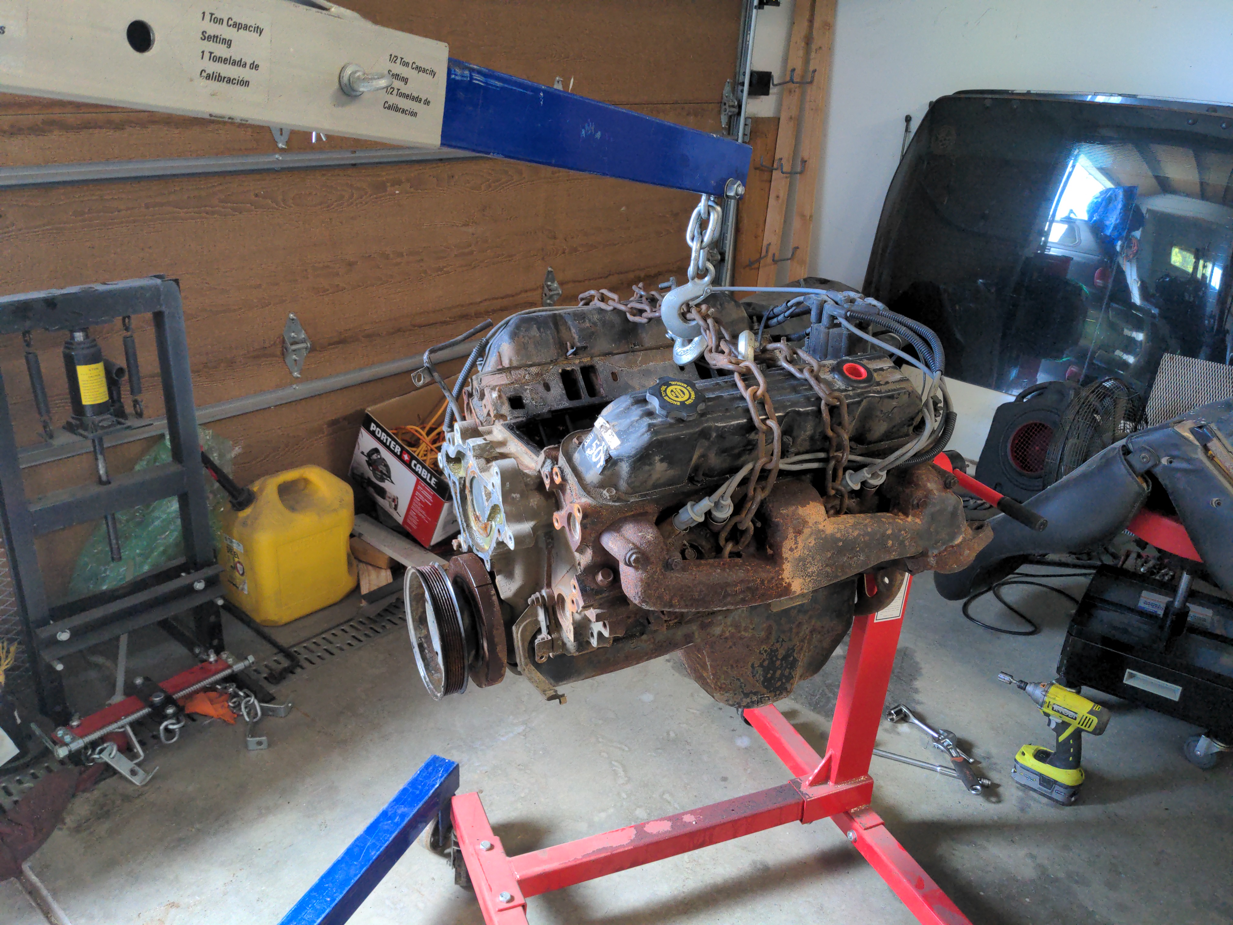 The first step was finding a rebuildable 5.2 V8 engine. Over the years, Dodge released a number of engine options, but for the sake of compatibility I was searching for a 5.2 Magnum V8 from their truck and van lines. This engine debuted in 1992 and was used in Dodge vehicles until 2003, so they aren't exactly rare. They are a standard pushrod-actuated design, which means a single camshaft uses a combination of lifters, pushrods, and rocker arms to actuate the engine valves (overhead cam engines are far more common these days, they are more complex but also more efficient and allow for interesting technology like variable valve timing or individual cylinder shutoff at crusing RPMs). That said, the older pushrod-style engines are notable for their longevity (200-300k miles without major service is common) and robustness (I've personally run a similar engine with two cylinders not firing, not pretty but it didn't leave me stranded). From the factory, the 5.2 Magnum V8s make about 230 HP and 295 ft-lbs, which is respectable for a smaller V8 of that era. These engines feature sequential fuel injection and an impressive (for the time) computer control system, and while they can respond quite well to tuning and modifications I want to stick close to stock power levels (I plan to use the original AX15 transmission in the truck and the V8 power output is very close to the peak power rating of the transmission; from the factory the V8 models had the NV3500, which can handle quite a bit more power).
It may be surprising that an engine covered with that much rust is usable, but this was all external - the engine turned over freely by hand, and as a bonus came with the intake, exhaust manifolds, and accessory brackets (the V6 brackets will also transfer over, so now I have an extra set of brackets as a backup). Total cost so far: $250.
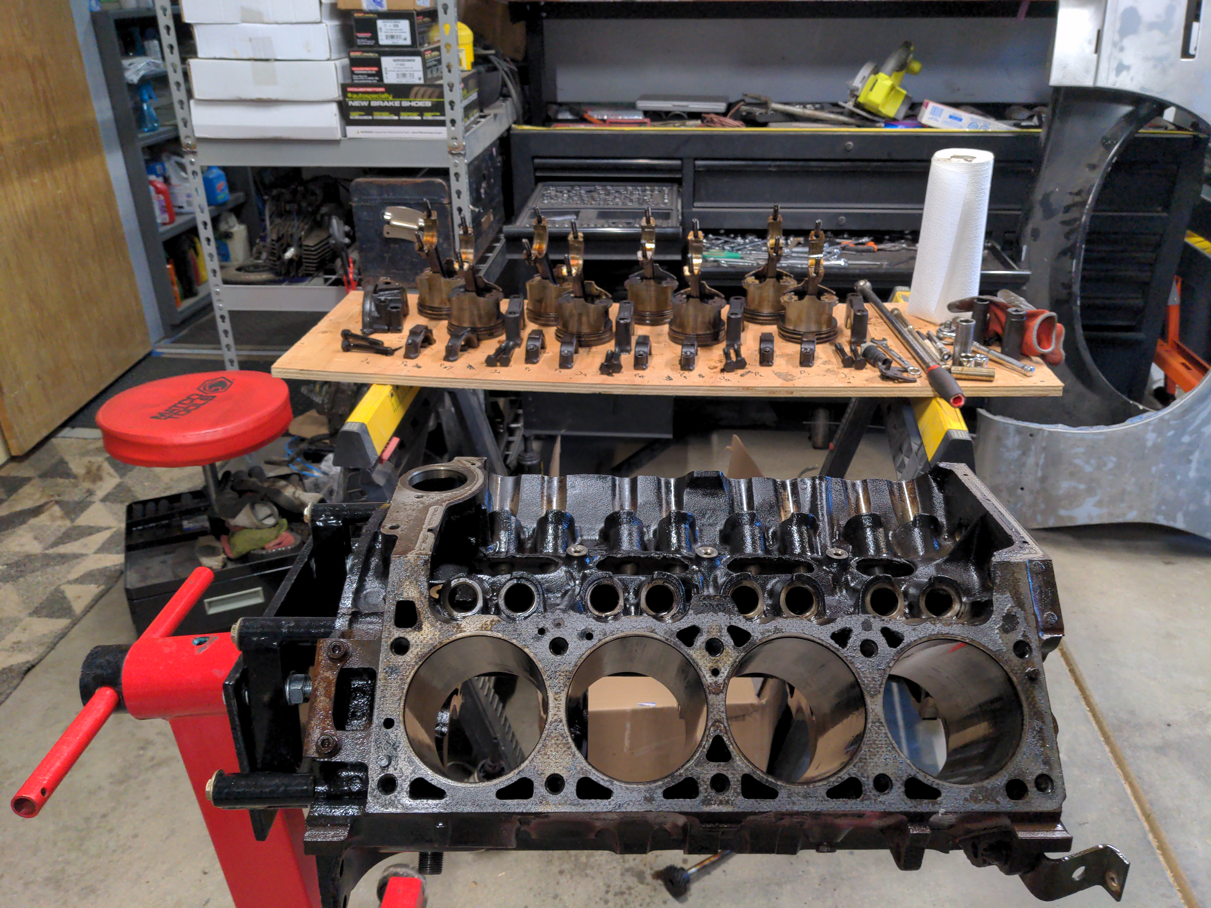 The first step was to disassemble the engine down to its base components. Many of these parts are not reusable by design (eg, bearings, piston rings, gaskets/seals) and despite the condition of the engine others needed to be replaced. I started with a complete engine, but after teardown and cleaning I found I could only reuse the engine block, connecting rods, crankshaft, timing cover, distributor intermediary shaft, intake, and injector assembly. Everything else needed to be replaced, including the heads. So, I set out ordering parts as cheaply as possible, and wound up spending about $1800 on the necessary components. The heads were particularly painful, as I had not planned on replacing those.
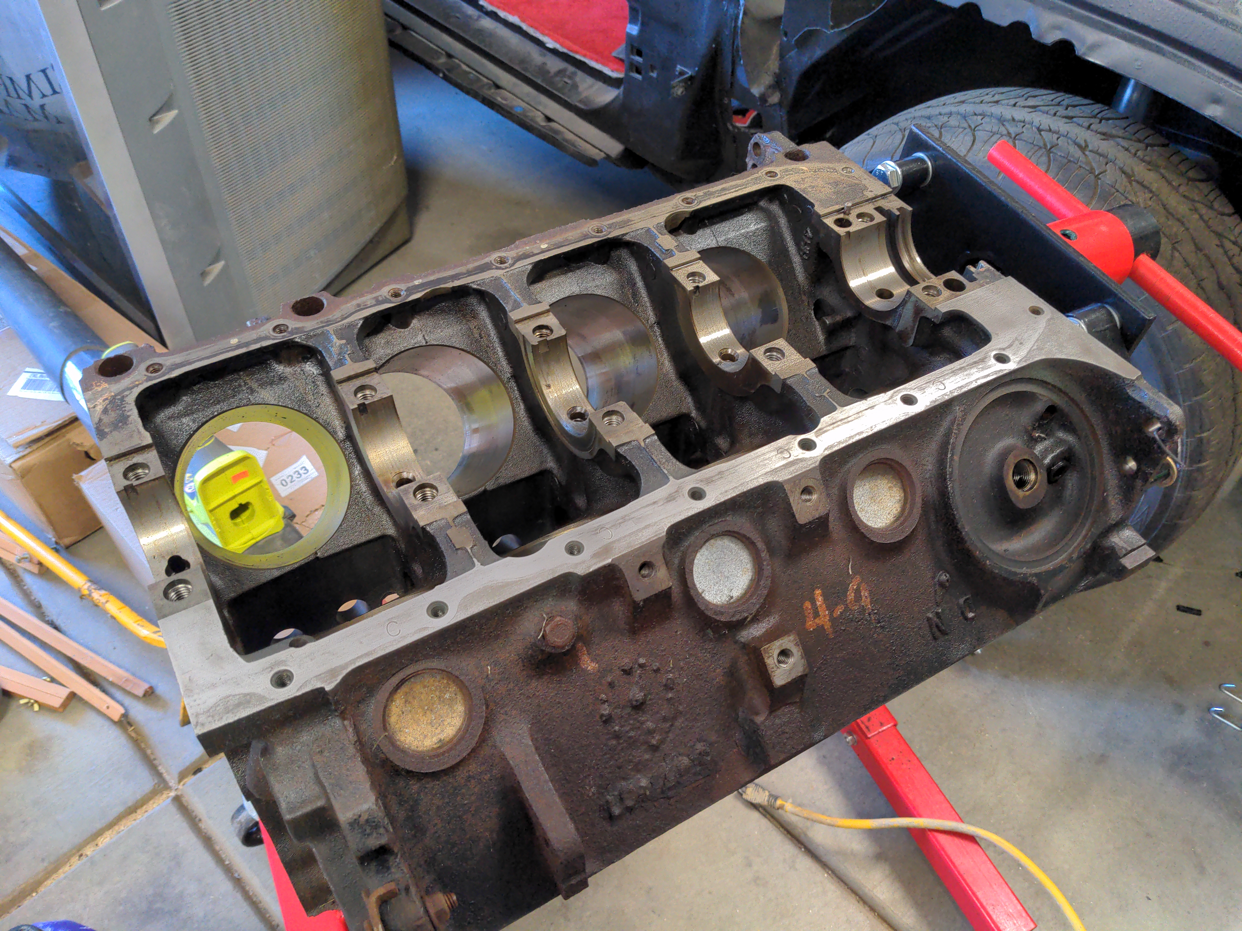 Here's a picture of the block after my cleanup efforts. Again, the exterior doesn't matter much here (you'll see why in some later photos) but the interior surfaces must be precisely fitted to their components (eg, the piston bores, piston rings, and pistons must all fall within specific tolerances or the engine will burn oil (too loose) or wear prematurely (too tight). As these older engines are a bit looser on tolerances (usually in the hundredths to thousandths of an inch), I was able to do most of this work to my satisfaction in my garage. However, for newer engines or high-performance race engines, more precision may be necessary. I didn't want to go overboard here, but even with my bare-bones machine work I spent about six hours getting everything dialed in. To my surprise, the cylinders on this engine had never been bored, meaning the engine had likely never been disassembled!
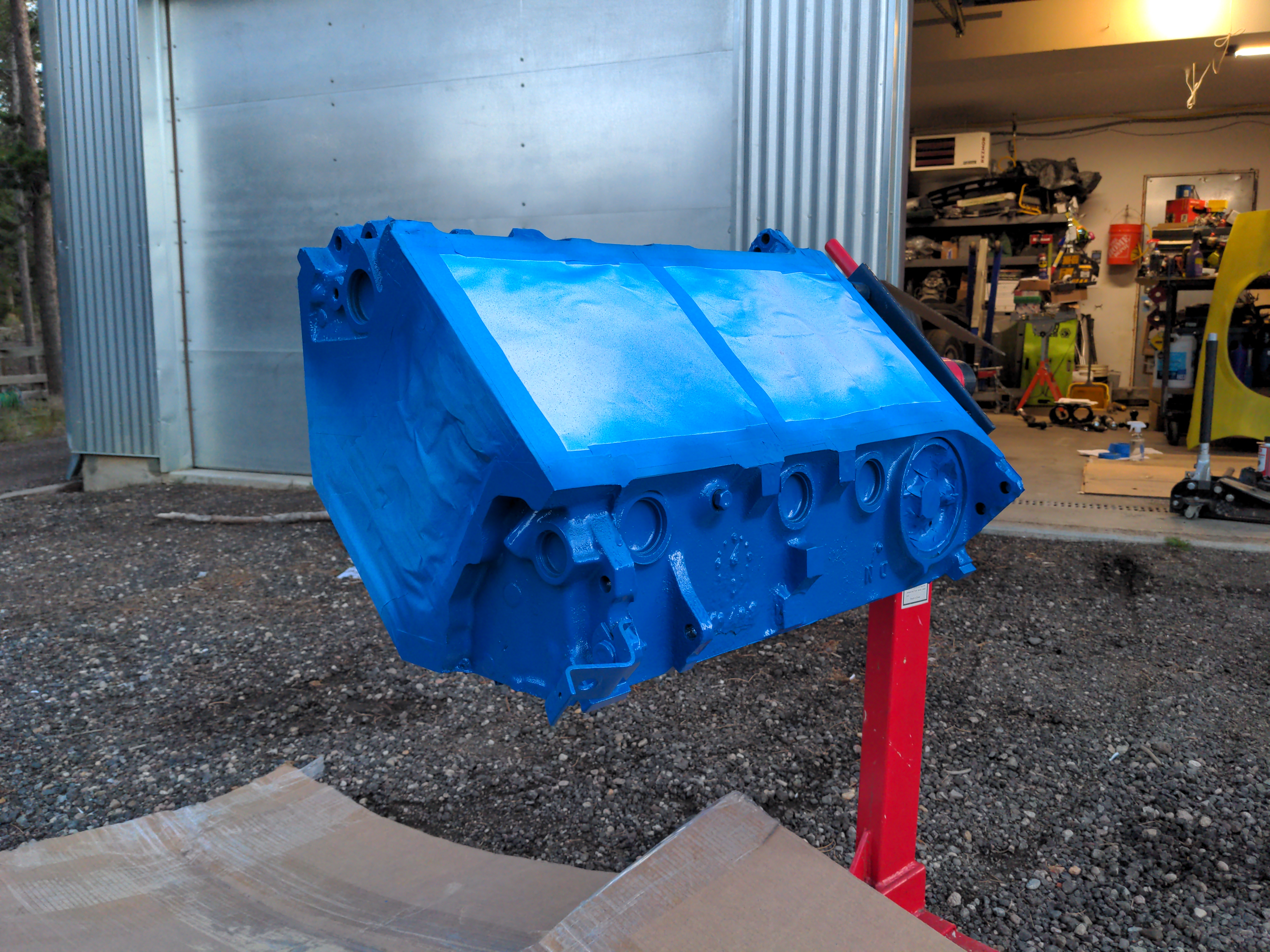 Remember when I mentioned I don't care too much about the exterior condition of the engine? That's because I'm painting it! Good high-temp engine paint adds a touch of class and will also help illuminate leaks (which I may very well have, since this is my first full engine build). I chose blue for the block, but there will be some surprises in place as the rest of the engine goes together. At this stage, the block itself is ready - time to start reinstalling parts.
Reinstalling parts is obviously the most fun part of the project! Typically, these engines go together in the following approximate order:
Bottom End (crank, crank bearings, bearing caps, connecting rods, pistons, piston rings, oil pump, camshaft, timing chain, timing cover, oil pan).
Top End (heads, lifters, pushrods, pushrod guides, valve springs, rocker arms, valve covers, intake manifold, distributor, injectors/injector assembly).
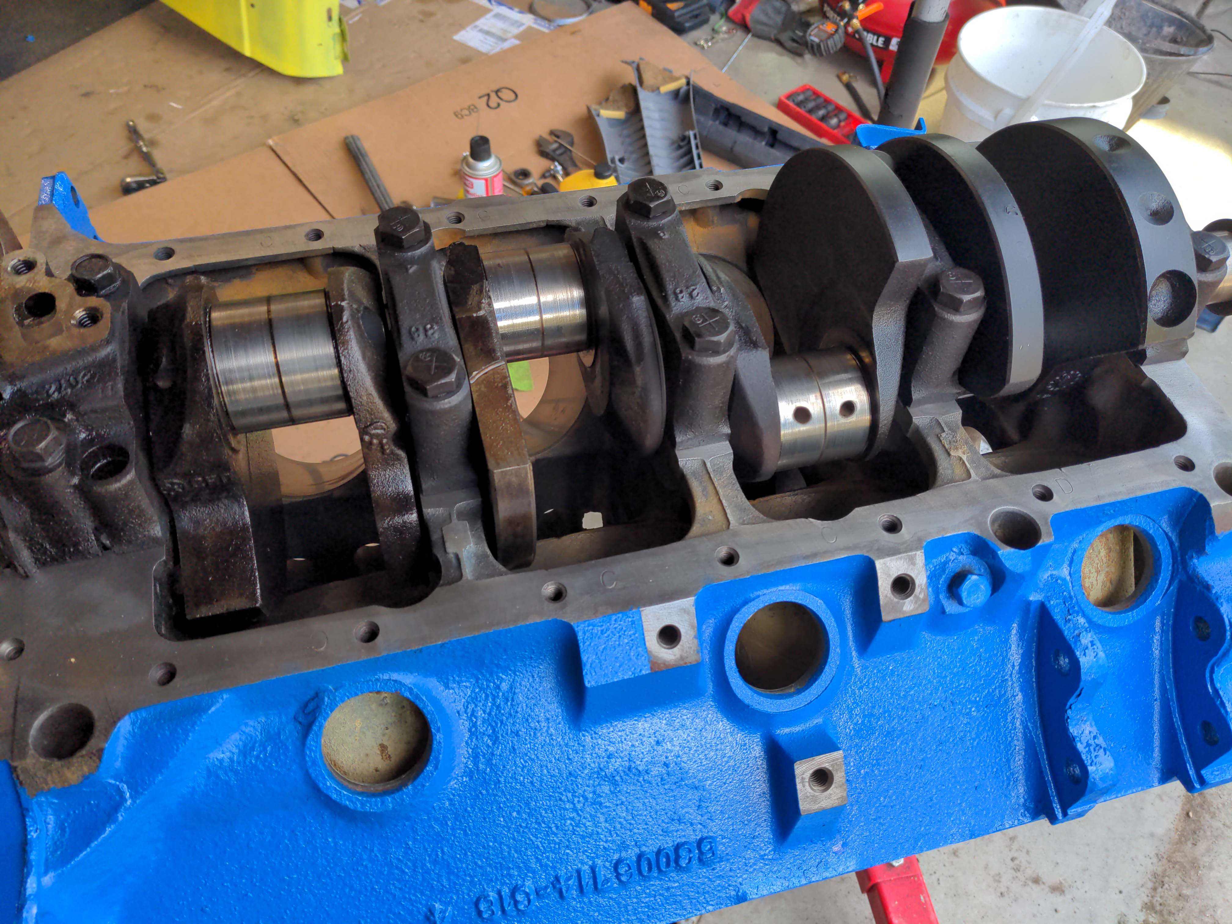 The crankshaft is the heart of an engine - it's what translates the explosive "downward" force of fuel igniting against a piston surface and converts it into a "rotational" force which is useful for actually, y'know, turning something (like a transmission in this case). Here you can see the crankshaft reinstalled and the bearing caps torqued down to spec. The bare areas are bearing surfaces for the connecting rodes, which go in next. The crankshaft rides on a series of bearings, which have groves for oil delivery. These are really just thin strips of various metals, but they play a critical role in engine operation. I had to take a lot of measurements here to ensure proper clearances - not just between the bearing surfaces and the crankshaft, but front-to-back as well (clearance between the crank and the bearing caps). A failure here would be especially galling because the engine needs to come back out of the truck and then has to be torn almost all the way apart, and every time I do that I have to replace a lot of single-use gaskets and fluids.
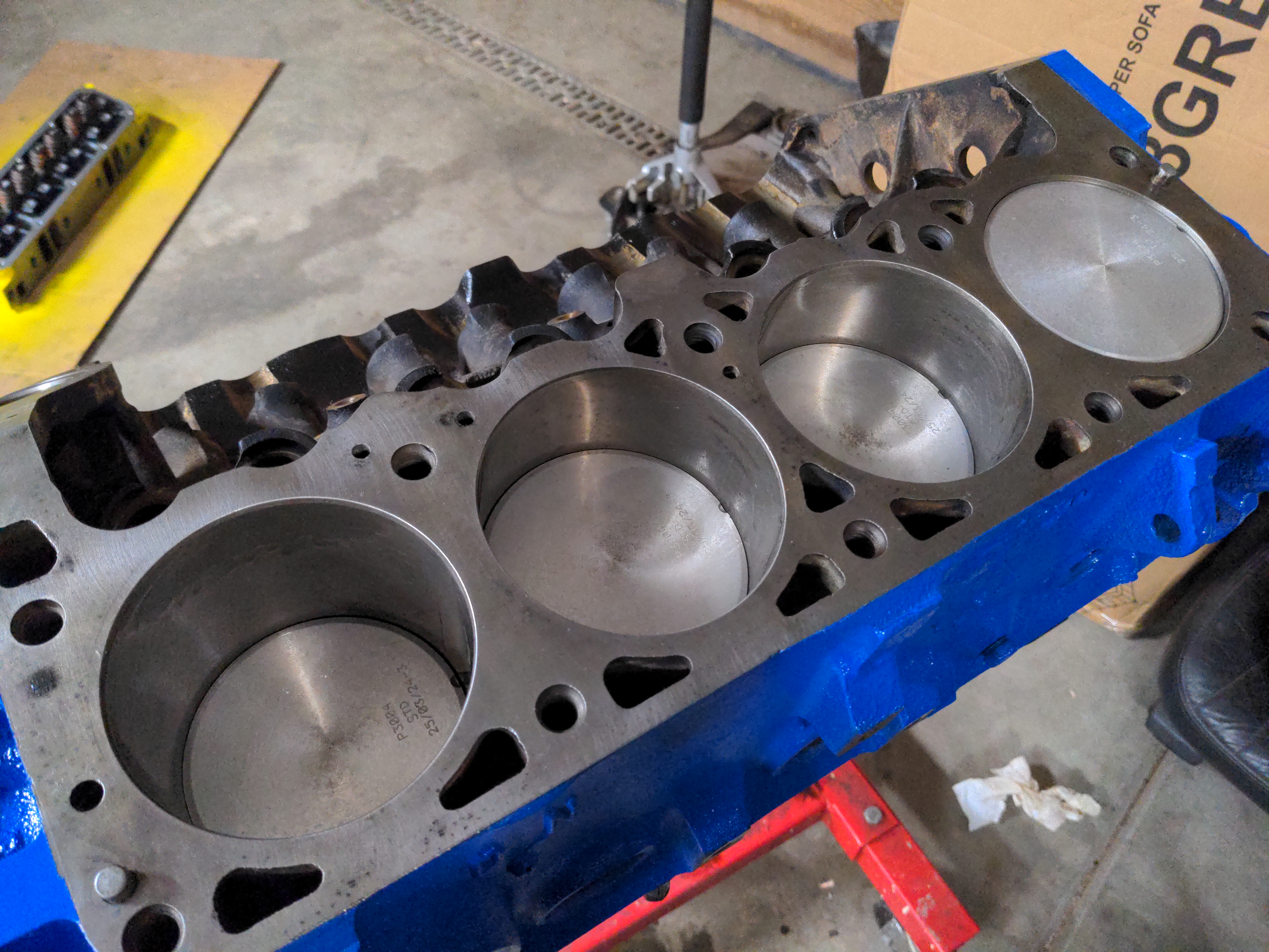 Next up are the pistons and connecting rods. In this photo you can really only see the tops of the pistons, but each one is tied to the crankshaft by a connecting rod (which rides on their own bearings and are all torqued to spec). Each piston has three piston rings, which work to control oil delivery between the cylinder walls and piston surface and prevents combustion gasses from leaking into the crankcase (note that no piston engine is perfect at this - there are always some losses). To install the piston, a tool is installed which compresses the piston rings and then the piston is gently tapped into the cylinder bore. It's tedious work and this is one area where I envy the folks building inline four cylinder engines, since they only have to do half as many of these!
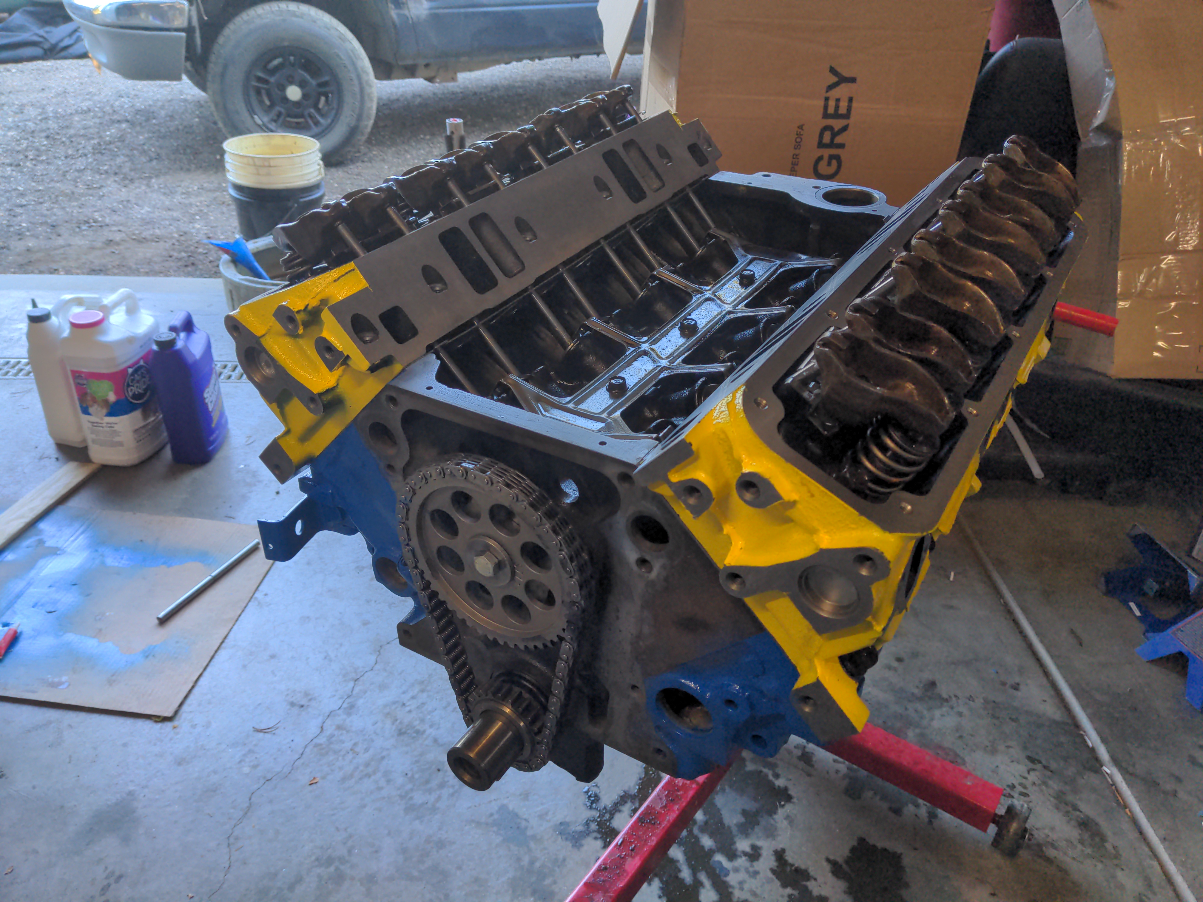 My next task was to install the camshaft and timing chain, although I don't have pictures of this process. The camshaft bearings were installed earlier on, so I used a cam installation tool (basically a 2' metal pole) to carefully guide the camshaft into the block. The camshaft is tied directly to the crankshaft by the timing chain, which ensures the crankshaft rotates twice for every rotation of the camshaft (this is a four stroke engine, like most automotive engines). The camshaft is one of the most important parts of the engine because it determines when and how much fuel/air mixture enters the engine and how quickly the burned mixture can exit. To provide an example, I have another V8 (5.7L in this case) installed in one of my other vehicles. From the factory, it made about 255 HP and 325 ft-lbs of torque. With a cam swap, it should now make about 370 HP and 410 ft-lbs of torque. That's all from a single part! However, as this is a computer controlled engine, I do have some limitations on how much I can upgrade the camshaft before it starts causing other issues. Since I'm also concerned about sending too much power to the AX15 transmission, I've just used a stock camshaft here.
I've also installed the heads here, along with the valve springs, lifters, pushrods, and rocker arms. This setup can be a bit tricky to picture, but to break it down simply - as the camshaft rotates, a lobe "pushes" the lifter further from the centerline of the camshaft. The lifter "pushes" the pushrod (hence the name), which then moves one side of the rocker arm up. The other side of the rocker arm moves down (just like a see-saw), and this forces the valve open. When the lobe rotates out from under the lifter, the valvespring forces the valve closed (this also keeps all the other parts in tight contact, as there's always pressure on one side of the system). In this engine, the lifter does double duty as an oiling solution by forcing oil up the hollow pushrod into the top of the cylinder head. At a nice crusing speed of say 1500RPM, this happens 12.5 times per second for each of the sixteen valves!
Also I painted the heads yellow. Heh.
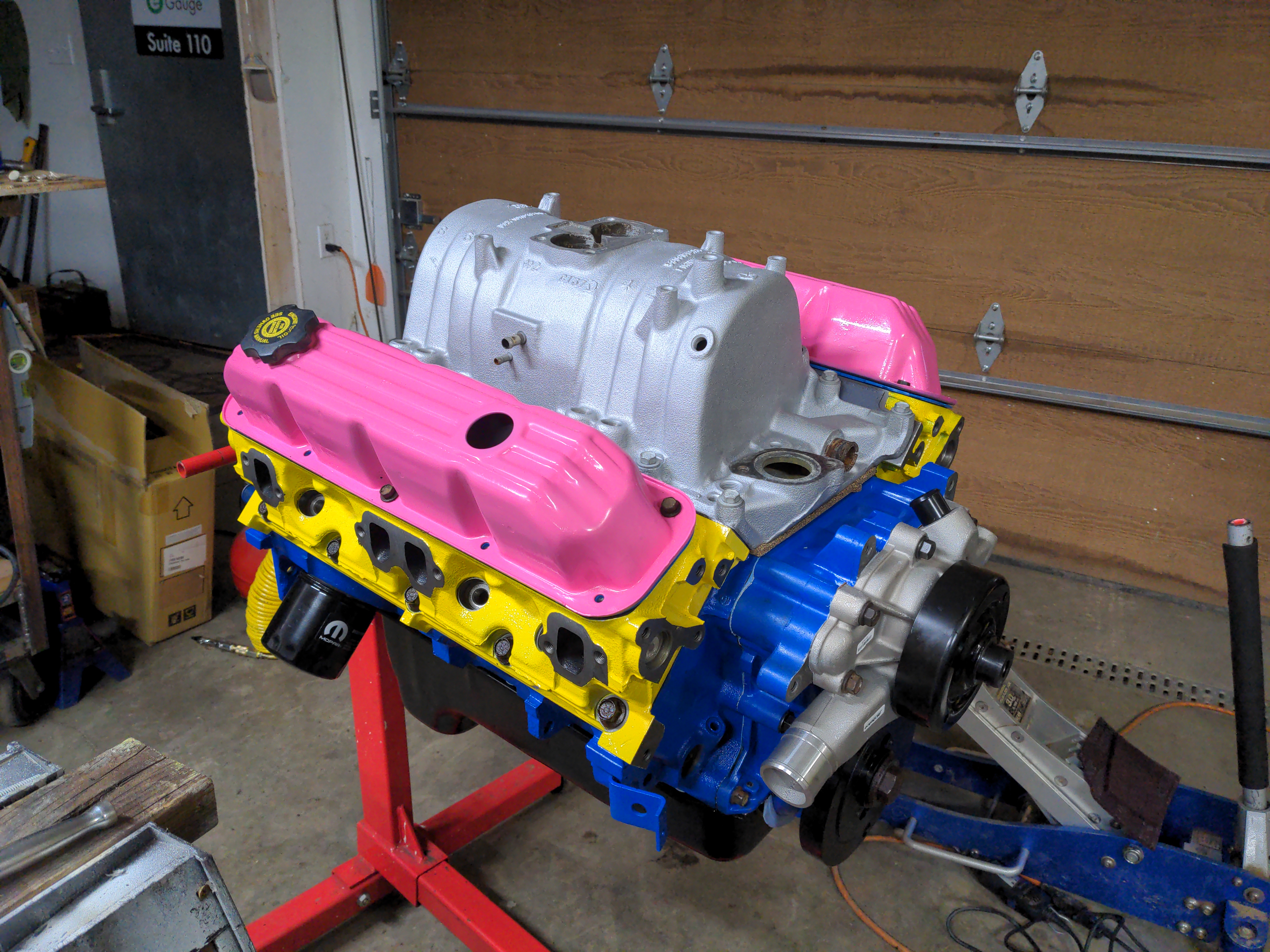 The last stage of this build was cleaning, painting, and installing the intake manifold. The intake directs air from a two-bore throttle body into each cylinder. An injector is installed in front of each cylinder's intake port, and it fires a fine mist of fuel into that cylinder right as the intake valve is opened by the movement of the camshaft. The intake manifold is usually raw aluminum and I did attempt to clean up the surface, but it was simply too stained to clean up well. Instead, I opted for a flat silver paint which at least looks somewhat close to a raw aluminum finish (I'm partial to the raw aluminum look over chrome).
What you see here is the current state of this engine. I have a few small details left (I need to install freeze plugs, install the oil dipstick, fill the engine with oil, clean and reinstall the injector assembly, install the throttle body, and install the distributor). Once that's done, I'll pull the truck's old 3.9 V6, along with the original clutch and flywheel. The newly rebuilt 5.2 will go in with a new clutch and flywheel, new motor mounts, new short-tube headers (which should give maybe 10 extra horsepower, and are the only performance improvement I made here), and all the accessories and accessory brackets from the V6 engine.
This has been a really rewarding (if tedious and difficult) project for me. I learned a lot about engine function and the attention to detail that's required. Would I do this again? Probably not, as I'd want my next engine build to be a much higher performance build. That requires more tools, more expensive parts, and probably multiple trips to a machine shop to have modifications made to more precise tolerances. However, I'm happy with the experience doing a low-budget build on my own, and it's taught me a lot I can use to help with diagnoses or repairs in the future!
Website coded by Delta Sierra, all content copyright Delta Sierra (unless otherwise noted). Hosting provided by Neocities.